Arduino and making original RC
Five years are passed, majoring electrical and electronic engineering. I am a novice at electronic work, so really first think don’t have sufficient parts for, but there are some servo motors for lego. [pictures↓]
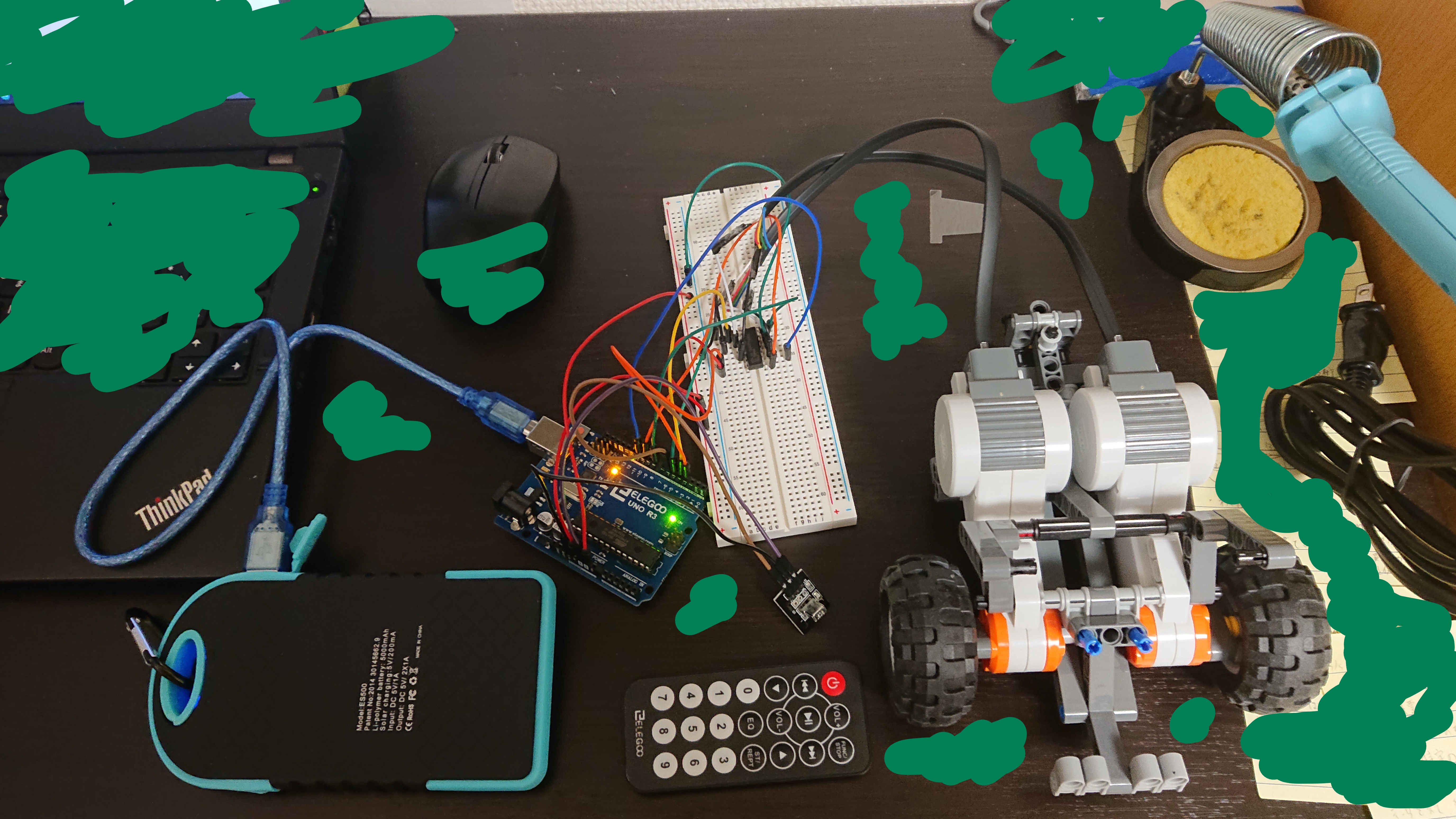
Infrared sensor, Lego Mindstorms Servo, Arduino, make me to come up with on IDEA, when tinkering Arduino starter kit.
Fundamental
First, as you know if you are Arduino-experienced, sketching LED Blinking Program. (Already completed, by only file opened.)
// the setup function runs once when you press reset or power the board
void setup() {
  // initialize digital pin LED_BUILTIN as an output.
  pinMode(LED_BUILTIN, OUTPUT);
}

// the loop function runs over and over again forever
void loop() {
  digitalWrite(LED_BUILTIN, HIGH);   // turn the LED on (HIGH is the voltage level)
  delay(1000);                       // wait for a second
  digitalWrite(LED_BUILTIN, LOW);    // turn the LED off by making the voltage LOW
  delay(1000);                       // wait for a second
}
Following that, Infrared Sensor worked. Starter kit illustrative codes are helpful thanks for its courteous instruction. They’re easy to understand for me. Infrared sensor give Arduino value of hexadecimal read infrared controller’s signal by using “IRremote.h” API. Its sample codes are that what signal of numbers of hexadecimal can be read on infrared sensor by outputting serial monitor (example picture)
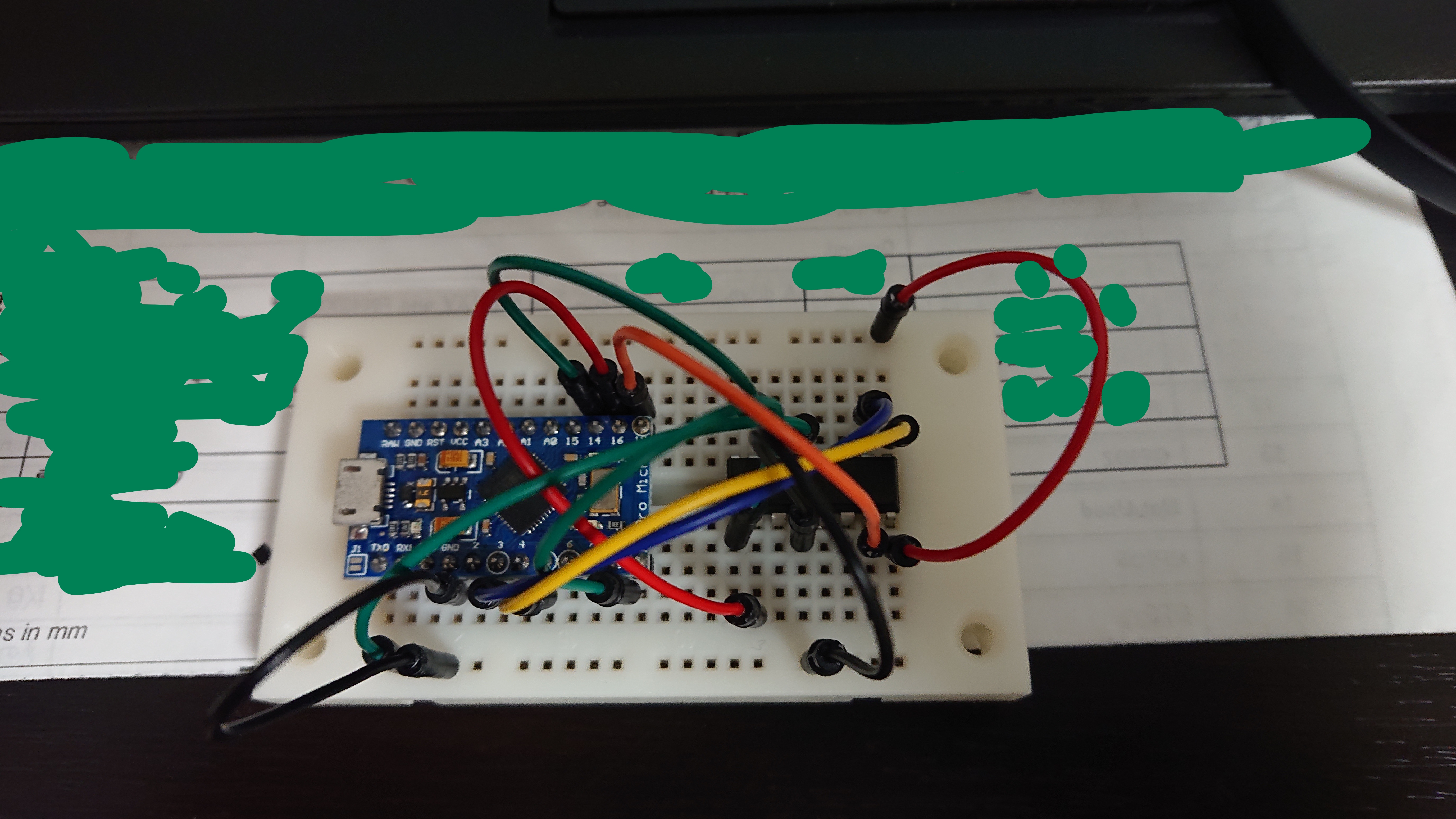
After them, write sketch of DC motor control by using Motordriver, then works all memorably!!
This is Pro Micro, Arduino compatible. Motor Driver is L293D.[picture]
I’ve heard it before not really exact embedded system has two roughly categorized types of malfunctional. Ones are caused by software trouble, others are hardware (circuits) mistakes, by complexed structure, components, elements wasting, for instance. They sometimes occurs both, leading harder problem.
Application
Infrared sensor, controller and DC Motordriver, separated two projects are consolidated. But hardware Problems are happened.
When running the program of RC car and operated it, it seems to be that I had made a few mistakes. It smells roasting circuit. I forgot implementation of electric resister. I start the measurement of electric resistance of wires and motor driver. Come to think of it, it might not be really. I should have estimated of current tolerance with by being wire’s and moter driver’s resistance as 0 ohm. Arduino’s voltage per pins are 5 V, and electrical resistance of circuits per pin are 10.9 ohm. Therefore, the current is,
$ \frac{5}{10.9} = 0.4587…\simeq0.46=460 $ mA
Due to Arduino’s current tolerance is 40 mA per pin, too higher current flows them.
THAT’S IT.
Improvements
Main issue is too upper current. For solving them, devising circuits surroundings are important. I think of it that using some element to amplify current from Arduino to motor driver. But lower 4.5 V voltage can’t drive NXT motors. No voltage drop higher than 0.5 V are required.
Transistor
Transistor is known as active component. [picture]↓
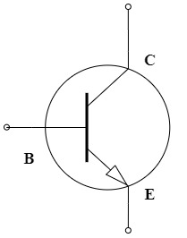
Implied is NPN form. Calculate putting resisters makes current control.
I should be going to do some experiments after somedays, and decide to concentrate on another experiments class at college, and start to think them from scratch.